PART 1 :: INTRO & BASIC TESTING
Difficulty Level: Beginner / Intermediate
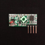
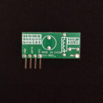
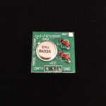
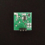
So like me, you too have happened upon this incredibly low priced set of wireless RF communication modules and now you’re sifting through Google search results to see if they really can do what they claim to. Let me save you the trouble and time and explain to you how I managed to get mine set up and working. Yes you heard right, they really do WORK. Maybe not up to 100 meters as some suppliers claim, but we can’t have it all for this price it seems.
Just one more quick thing before we get started, I don’t claim to be an expert on the subject of electronics. I’m just someone who has a passion for it and wants to contribute to the ever expanding online library of resources and tutorials. So if you do happen to find any mistakes or improvements I can make, please let me know and I’ll definitely take them into consideration. Also this is my first blog, so go easy on me.
HOOKUP GUIDE
- 1x Set of 433MHz RF-Link Tx / Rx Modules
- 1x Breadboard
- 5VDC Supply Voltage
- Breadboard Jumper Wires
- 1x BC337 NPN Transistor
- 1x 1k-Ohm 1/4W Resistor
- 1x LED
- 1x 470-Ohm 1/4W Resistor
- 1x Tactile Push-button
- Step 1 – Power for your circuit :
We will be powering this test circuit with 5VDC. So you can either power it directly from any 5V USB source (no need for the 5V regulator), or use a higher DC voltage with a 5V regulator to get the required 5VDC. In my schematic I am using a common 7805 regulator to step down the 7.4V of some Lithium Ion batteries I have connected. The transmitter module has an input voltage range of 3V to 12VDC, while the receiver module has a typical working voltage of 5VDC. - Step 2 – Tx + Rx Module Power :
Connect both modules to Gnd and +5VDC rails of your breadboard. - Step 3 – Wire up transmit button :
Next connect your tactile push-button to the DATA pin of the transmitter and +5VDC supply rail. This is how we will be transmitting high pulses to the receiver. - Step 4 – Wire up receiver LED :
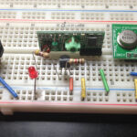
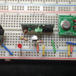
Finally we need to build the part of the circuit that shows us we’re actually receiving wireless data. The DATA output pin of the Receiver Module is not able to light up an LED by itself, so we need to add a transistor stage in between. Connect the base of the BC337 through a resistor to the DATA pin of the receiver. The emitter goes straight to ground and the LED is connected from our +5VDC supply rail to the collector through a series current limiting resistor.

