
Features / Specs
- Manufacturer: Seeed Studio
- Part Number: 113991115
- Main Chip: Espressif ESP32-S3R8 (Xtensa LX7 32-bit dual-core processor, up to 240 MHz)
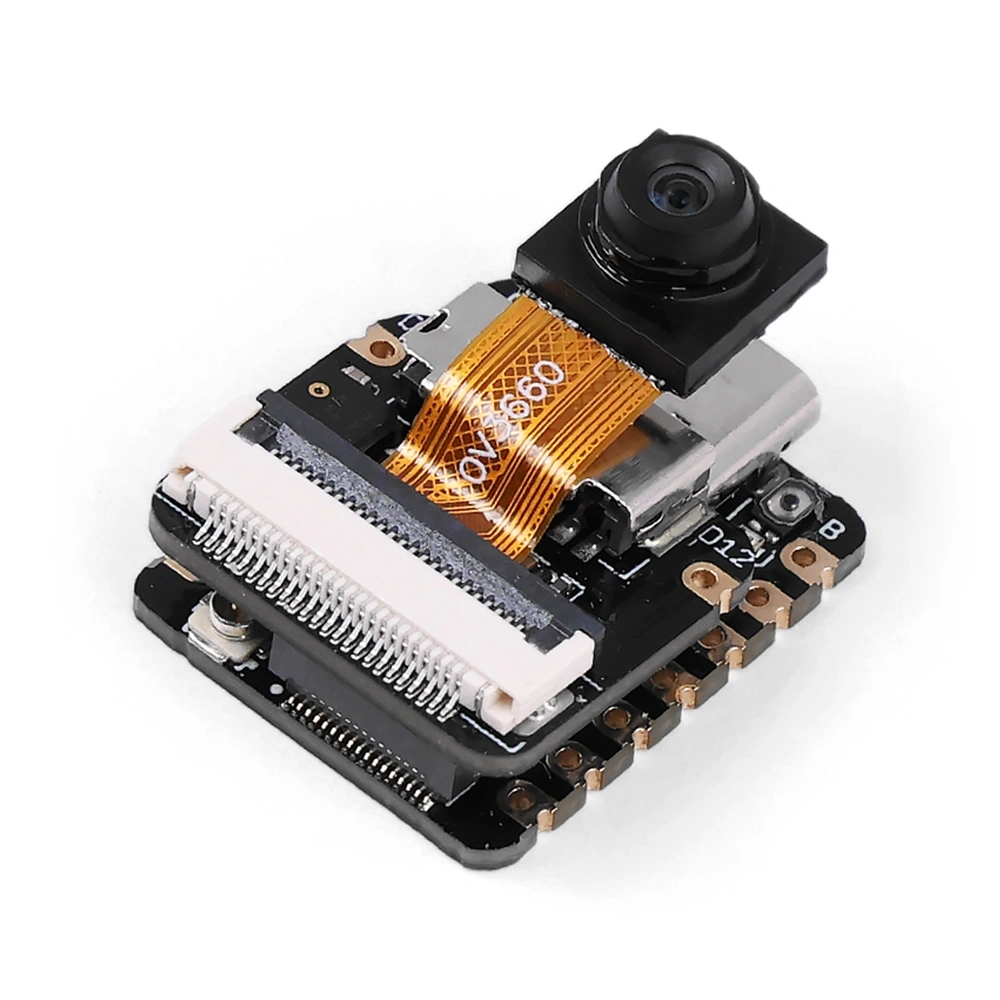
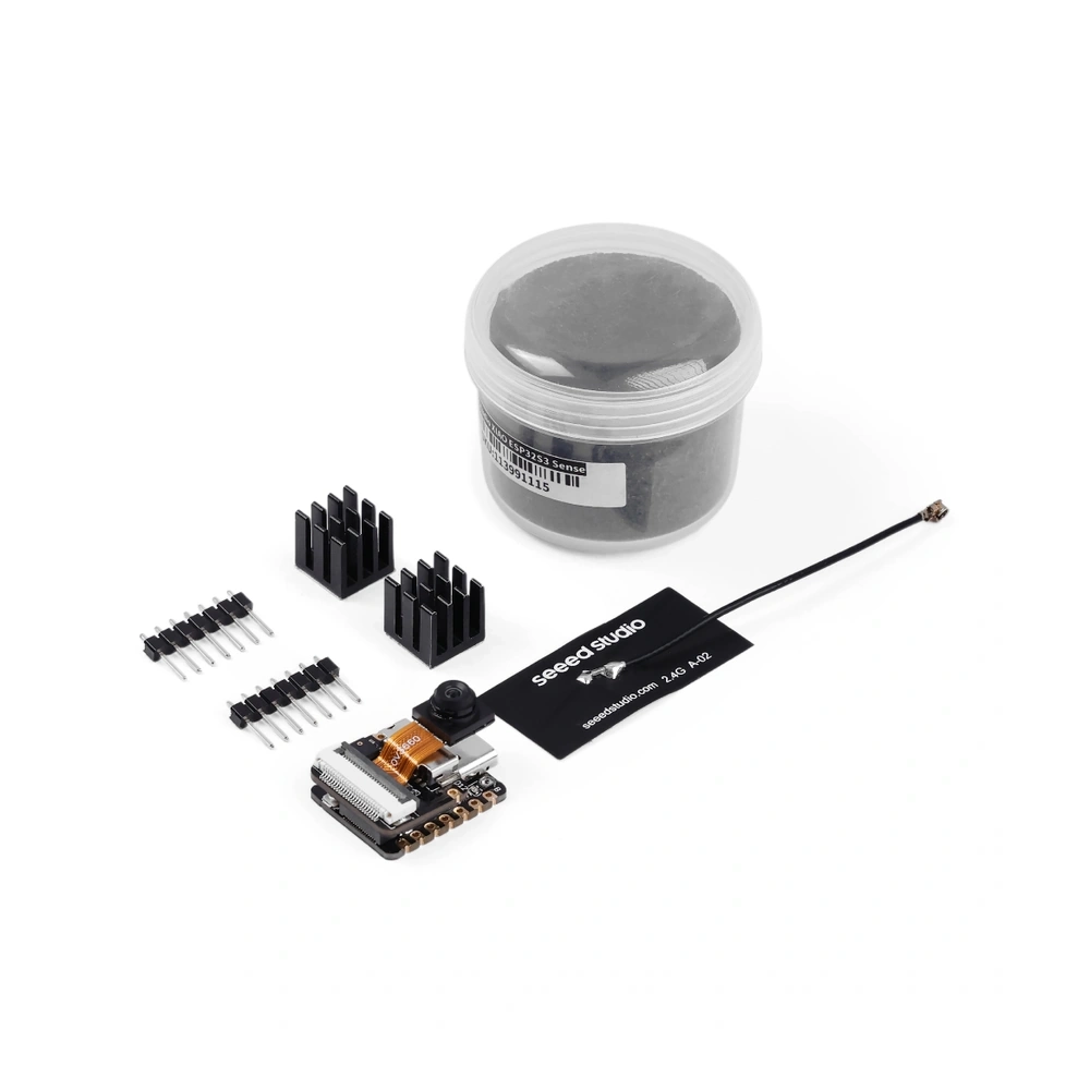
- Antenna: External FPC antenna (Seeed XIAO FPC Antenna A-02, included), connects to the onboard Male IPEX MHF-I / U.FL Socket (Hirose U.FL-R-SMT-1) – the board has no onboard antenna
- Flash Memory: 8 MB (onboard, Quad SPI, GD25Q64ENIGR)
- ROM: 384 kB
- SRAM: 512 kB (plus 16 kB RTC SRAM)
- PSRAM: 8 MB (in-package, Octal SPI)
- USB Interface: USB Type-C, connected directly to the ESP32-S3’s native USB (USB Serial/JTAG controller and full-speed USB OTG) – no USB-to-serial chip
- Power Input Options:
- USB Type-C Socket: 5 V
- 5V Pin: Power input/output, connected directly to the USB Type-C VBUS line – no voltage on it when running from the battery; to feed 5 V in, fit a diode (Schottky, signal or power), anode to the source and cathode to this pin
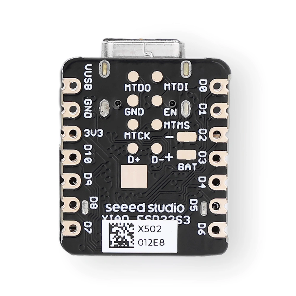
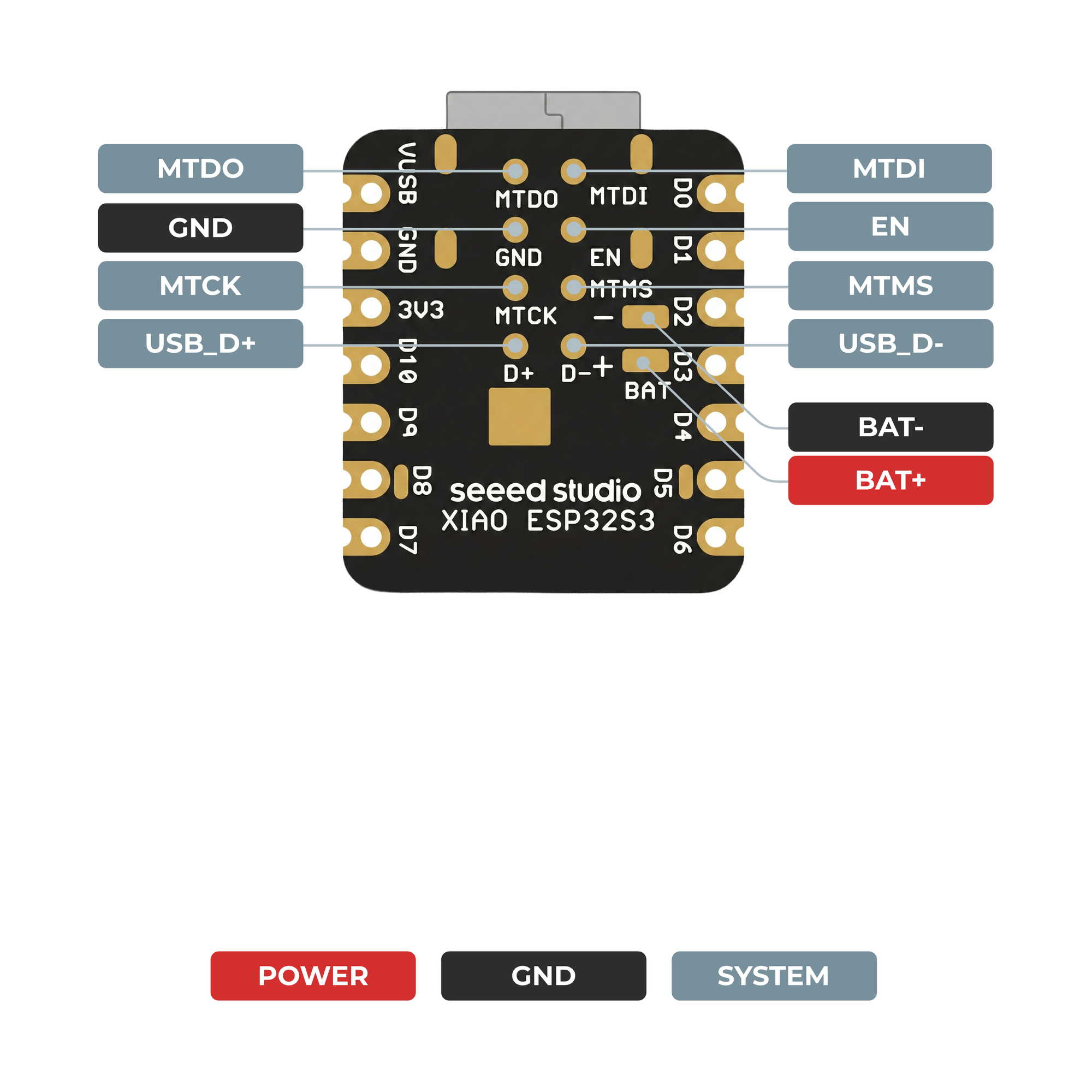
- Battery Pads: 3.7 V lithium battery, soldered to the BAT pads on the back of the board (no battery connector), charged by the onboard SGM40567-4.2 charger at about 110 mA
- Power Switching: Runs from USB (or the
5Vpin) when connected, and from the battery otherwise – a diode stops the battery feeding back out of the5Vpin - 3V3 Pin: Regulated 3.3 V output from the onboard SGM6029 buck converter, up to 600 mA (Seeed schematic note)
- Operating Voltage Range (Chip): 3.0 – 3.6 V (supplied at 3.3 V by the onboard regulator)
- I/O Logic Level: 3.3 V – inputs are rated to a maximum of VDD + 0.3 V, so the pins are not 5 V tolerant
- Deep Sleep Current (Typical): 3 mA (with the camera expansion board fitted)
- Communication Interface: USB / UART
- Programming Support: Arduino / MicroPython / SenseCraft AI (no-code vision and audio models)
- Bootloader Mode: Hold Boot while connecting USB, or hold Boot and press Reset
- Operating Temperature Range: -20 °C to +65 °C
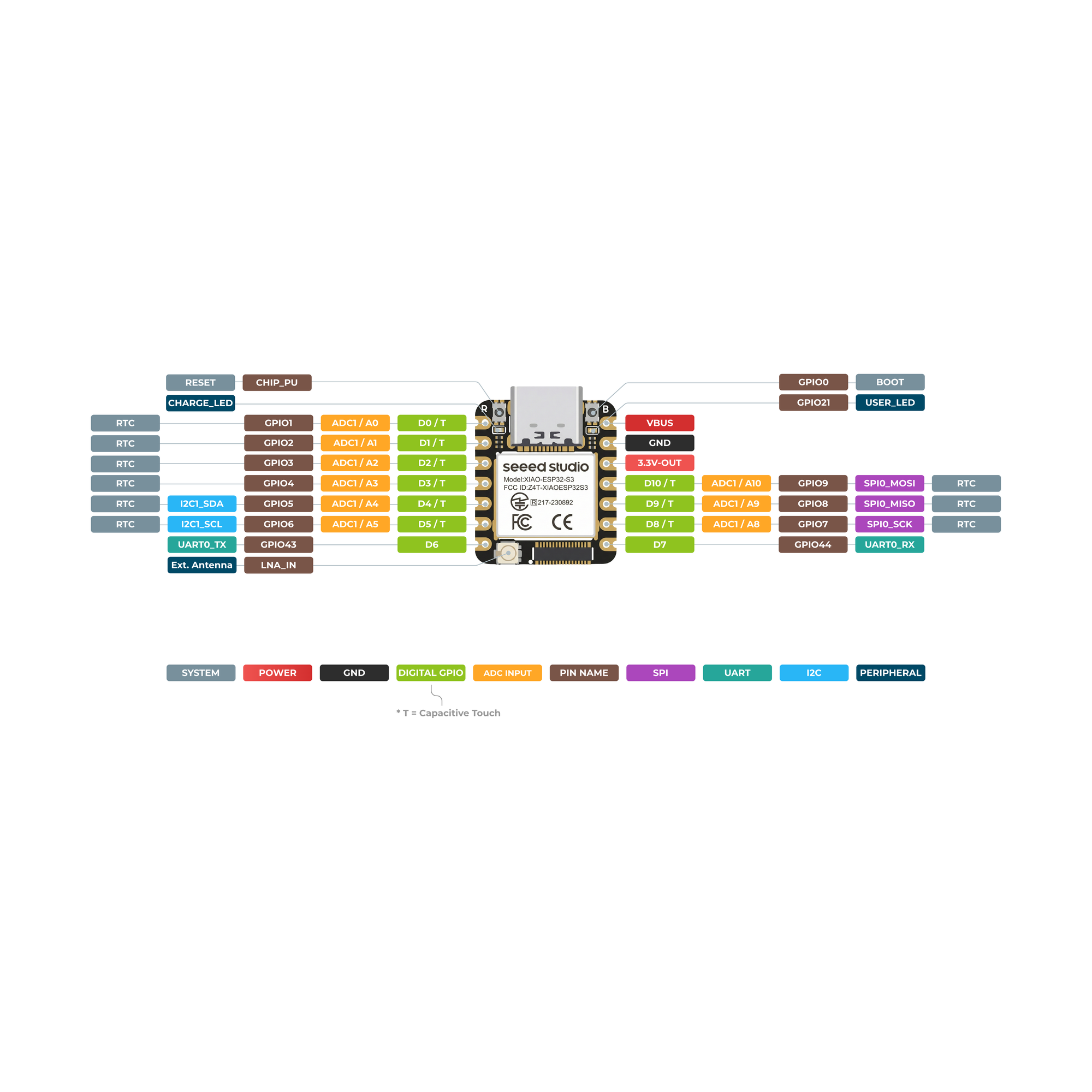
- Usable Peripherals (This Board): 11x programmable GPIOs (all PWM-capable) / 1x UART (UART0 on
D6/D7) / 1x I2C / 1x SPI (shared with the microSD slot) / 1x I2S (used by the onboard microphone) / 9x ADC channels / 9x capacitive touch channels - Full Chip Capabilities (Not All Exposed on This Board): 45x programmable GPIOs / 4x SPI (2 reserved for flash/PSRAM access, 2 general-purpose) / 3x UART / 2x I2C / 2x I2S / 2x 12-bit SAR ADC, up to 20 channels / 14x capacitive touch IOs / full-speed USB OTG + USB Serial/JTAG / TWAI (CAN 2.0) / LED PWM (up to 8 channels) / 2x MCPWM / RMT / PCNT / SD/MMC host (2 slots) / LCD interface / 8-bit to 16-bit DVP camera interface
- Security Features (Chip): Secure boot / flash encryption / 4 kbit eFuse (OTP) / AES, SHA, RSA and HMAC acceleration / digital signature / random number generator
- GPIO:
- Usable: 11x programmable GPIOs on header pins
D0–D10(GPIO1/GPIO2/GPIO3/GPIO4/GPIO5/GPIO6/GPIO43/GPIO44/GPIO7/GPIO8/GPIO9) - Analog:
D0–D5andD8–D10(9x ADC channels) - Touch:
D0–D5andD8–D10(9x capacitive touch channels) - Strapping Pins:
GPIO0(Boot button) /GPIO3(D2) /GPIO45/GPIO46(not broken out, left at their internal defaults) – sampled at reset to set the boot mode, flash voltage and JTAG source, so keep external circuits from pulling them the wrong way at power-up - Used Onboard:
GPIO26–GPIO32(flash / PSRAM SPI bus) /GPIO33–GPIO37(Octal PSRAM) – not broken out; Espressif says not to use them for any other purpose - Used by Camera:
GPIO10–GPIO18/GPIO38/GPIO39/GPIO40/GPIO47/GPIO48– through the B2B connector, not on the headers - Used by microSD:
GPIO21(CS, shared with the user LED) plus the header SPI pinsD8/D9/D10(GPIO7/GPIO8/GPIO9); cutting theJ3pad on the expansion board disconnects the card’s pull-up resistors – the header SPI pins then work normally and the card slot is disabled - Used by Microphone:
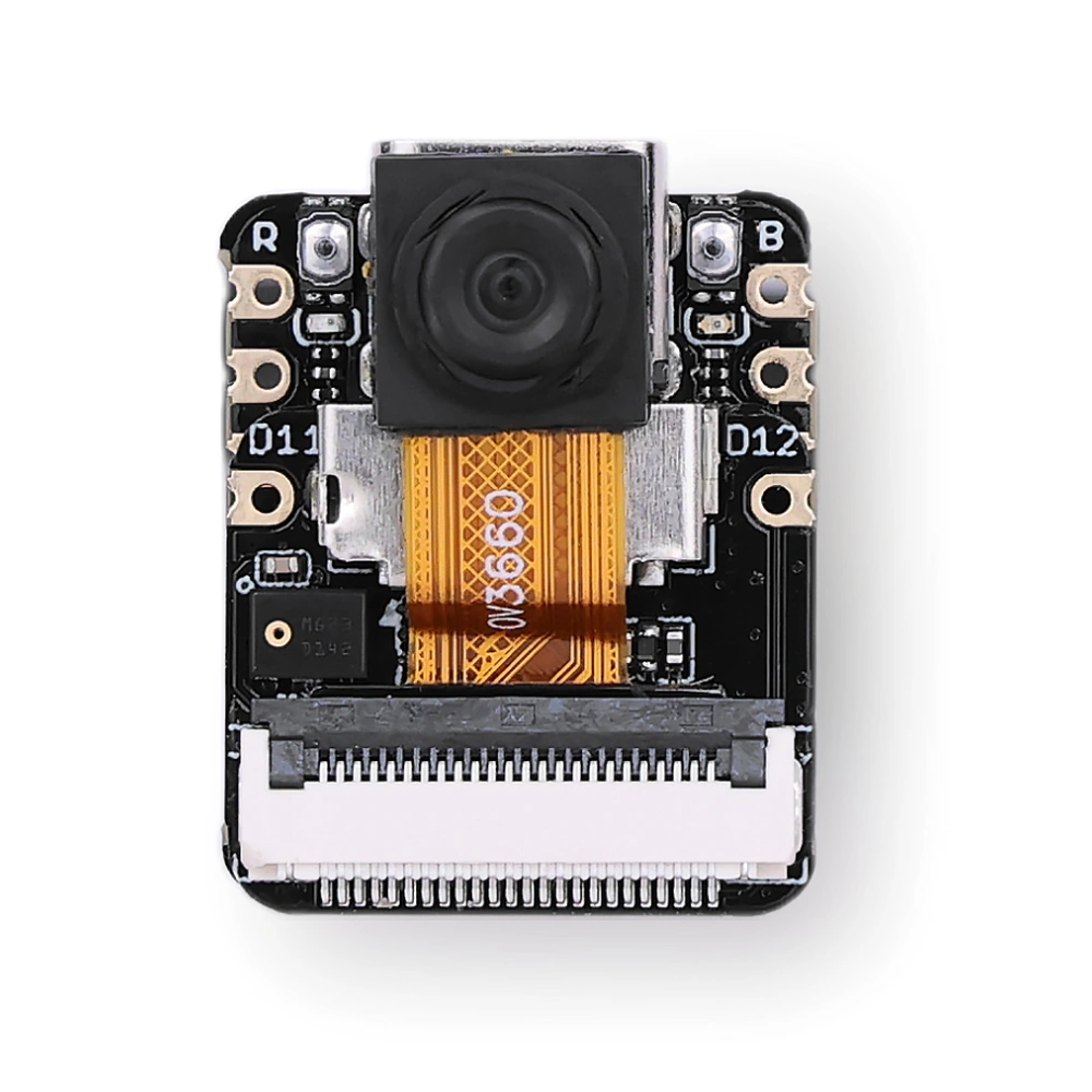
GPIO42(PDM clock) /GPIO41(PDM data), also brought out to theD11/D12pads on the expansion board; cuttingJ1/J2frees them for other uses but disables the microphone (these two pins have no ADC) - Series Resistor:
D6(TX) connects to the chip through a 499 Ω resistor – fine for UART, but it limits the currentD6can supply - Shared with USB:
GPIO19/GPIO20(USB D- / D+) – used by the USB Type-C port, not on the headers; also on theD-/D+pads on the back - Battery Monitoring: None – no GPIO is wired to read the battery voltage
- Debug: USB Serial/JTAG over the USB Type-C port, plus JTAG pads on the back (
MTMS/MTDI/MTCK/MTDO; alsoEN/GND) – the JTAG pins areGPIO39–GPIO42, shared with the camera and microphone
- Usable: 11x programmable GPIOs on header pins
- Onboard Peripherals:
- Camera: Detachable camera module on the expansion board (DVP interface) – OV3660 (3 MP, 2048 x 1536, fixed focus)
- Microphone: Digital PDM MEMS microphone (MSM261D3526H1CPM) on the expansion board
- microSD Card Slot: On the expansion board, SPI mode, supports cards up to 32 GB (FAT)
- Buttons: Reset / Boot (
GPIO0) - LEDs: Yellow user LED on
GPIO21, lit when driven low (shared with the microSD CS) / red charge LED
- Pin Description: Pinout diagram in the product images; full pin map in the linked Seeed wiki
- Certifications: FCC (FCC ID Z4T-XIAOESP32S3) / CE / Japan MIC (217-230892)
- Dimensions (L x W x H): ~(21 x 17.8 x 15 mm) with the expansion board and camera fitted
- Number of Pins: 2x 7 pins (14 total)
- Header Pin Pitch: 2.54 mm
- Pin Row Spacing (Centre to Centre): 15.24 mm
- WiFi Standards: IEEE 802.11b/g/n
- WiFi Frequency Band: 2.4 GHz
- WiFi Channel Bandwidth: 20 MHz / 40 MHz
- WiFi Data Rate (Max): 150 Mbps
- WiFi Transmit Power (Max): +21 dBm (802.11b) / +19.5 dBm (802.11n)
- WiFi Modes: Station / SoftAP / Station + SoftAP
- WiFi Security: WPA2-PSK / WPA2-Enterprise / WPA3-PSK / WPA3-Enterprise
- Bluetooth Version: Bluetooth 5 (LE), Bluetooth mesh
- Bluetooth Data Rates: 125 kbps / 500 kbps / 1 Mbps / 2 Mbps
- Bluetooth Transmit Power (Max): +20 dBm
- Bluetooth Receive Sensitivity: -104.5 dBm @ 125 kbps / -93.5 dBm @ 2 Mbps
- Bluetooth LE Features: Advertising extensions / multiple advertising sets / simultaneous advertising and scanning
- Antenna Sharing: WiFi and Bluetooth share the one antenna, through the chip’s internal coexistence mechanism
Resources
- Seeed Studio XIAO ESP32-S3 Series Getting Started (Wiki)
- Seeed Studio XIAO ESP32-S3 (Sense) Pin Multiplexing (Wiki)
- Seeed Studio XIAO ESP32-S3 Sense Product Datasheet
- Seeed Studio XIAO ESP32-S3 Sense Schematic Rev 1.3
- Seeed Studio XIAO ESP32-S3 Sense Expansion Board Schematic v1.2
- Espressif ESP32-S3 Series Datasheet v2.2
- OmniVision OV3660 Image Sensor Datasheet