


The JSN-SR04T-A1 is a high-performance, non-contact ultrasonic distance measurement module designed for reliable operation in demanding environments. The sensor supports a measuring range of 25 cm to 600 cm, delivering stable and accurate performance across a wide detection area. Built around a high-performance processing core and quality electronic components, the module offers excellent long-term reliability and extended service life. The unit features an industrial-grade waterproof ultrasonic transducer, making it suitable for outdoor and harsh-environment applications. An integrated high-precision distance measurement algorithm ensures strong noise resistance and stable readings, while optimized power management keeps overall consumption low.
Features / Specs
- Manufacturer: Shenzhen Jieshenna Technology Co., Ltd. (JSN)
- Part Number: JSN-SR04T-A1-02
- Configuration: Object Measurement Version (UART Controlled)
- Operating Voltage Range: 3.3V – 5.5VDC
- Operating Current: ≤ 10mA
- Standby Current: ≤ 8µA
- Maximum Range: 600cm (6 meters)
- Minimum Range: 25cm
- Accuracy (@ 25°C, 65% RH): ± (1cm + 0.5% of measured distance)
- Resolution: 1mm
- Measurement Time: ≤ 70ms
- Detection Angle: ~45°
- Temperature Compensation: Yes, within operating temperature range
- Output Mode: UART controlled output
- Operating Temperature Range: -15℃ to +60℃
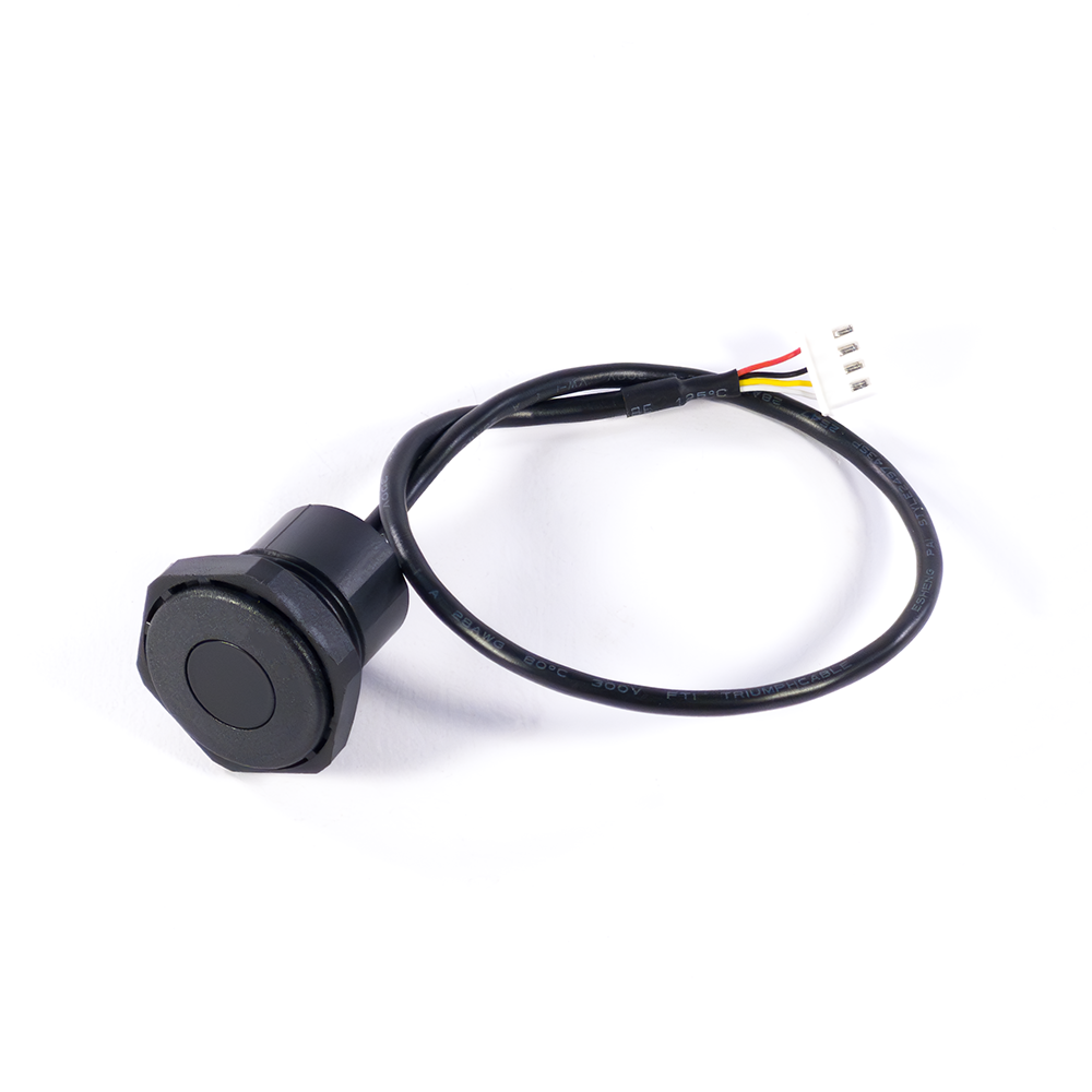
- Connector Type: 4-Pin 2.5mm Pitch XH Connector
- Cable Length: ~30cm
- Dimensions: See product images
Operation Overview
UART Controlled Output Mode:
- This mode operates using command-based UART measurement, meaning the sensor remains idle until it receives a valid trigger command.
- A measurement cycle is initiated only when the module receives the command 0x00 on the “RX” pin, or when a low-level pulse ≥10 µs is applied to the “RX” pin.
- Upon receiving a valid trigger, the module performs one complete distance measurement cycle and then transmits the result through the “TX” pin.
- The communication format is 9600 bps, 8 data bits, no parity, 1 stop bit (9600–8–N–1) using TTL logic levels.
- The output frame consists of 4 bytes: 0xFF (header) + High Byte + Low Byte + Checksum, where the checksum is the lower 8 bits of the sum of the first three bytes.
- A minimum interval of greater than 70 ms between trigger commands is required to ensure reliable measurement operation.
- Because measurements occur only when commanded, this mode allows precise control over sampling frequency and helps reduce overall power consumption.
- This mode is well suited for polled measurement systems, battery-powered designs, or applications where multiple sensors share a UART bus and must be individually triggered.