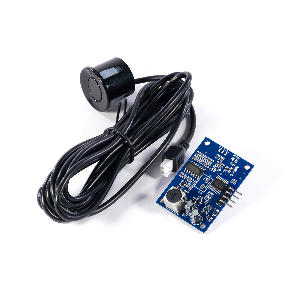


The JSN-SR04T waterproof ultrasonic sensor consists of a waterproof ultrasonic transducer (combined transmitter and receiver) and a separate control board. The control board drives the transducer and provides a standard interface for connection to a microcontroller, allowing users to trigger measurements and read distance data. The sensor measures distance using high-frequency, inaudible ultrasonic waves. When triggered, the module emits a burst of ultrasonic pulses and listens for the reflected echo from a target within range. The distance is calculated by measuring the time between transmission and reception of the ultrasonic signal.
Features / Specs
- Manufacturer: Shenzhen Jieshenna Technology Co., Ltd. (JSN)
- Part Number: JSN-SR04T-V3.3 (Latest board revision with improved features)
- V3.3 Improvements: Added temperature compensation for more accurate distance readings / Improved DC-DC power anti-interference for better stability / Built-in same-frequency interference filtering for cleaner signals / Adjustable detection angle for different applications
- Operating Voltage Range: 3.0V – 5.5VDC
- Operating Current: < 8mA
- Ultrasonic Transceiver Frequency: 40kHz
- Maximum Range: 500cm (5 meters)
- Minimum Range: 23cm
- Accuracy (Long Range): ± 1cm
- Resolution: 1mm
- Detection Angle: 75°
- Input Trigger: TTL pulse ≥ 10µs / Serial command: 0x55
- Output Signal: Pulse width voltage signal (TTL) / UART serial output (depending on mode setting)
- Operating Temperature Range: -20℃ to +70℃
- Cable Length: ~2.5 Meters
- PCB Dimensions: ~(41.3mm x 28.5mm x 17.8mm)
- Mounting Hole Diameter: ~2.5mm
- Mounting Hole Spacing (Center to Center): ~(36mm x 23.3mm)
Operation Overview
The SR04T supports multiple output configurations to suit different integration requirements – from classic pulse-width measurement to UART serial and simple threshold switching.
Mode 0 – Open (Default Pulse Output):
- This is the default operating mode and does not use UART communication. It operates using a standard trigger/echo timing method.
- The “TRIG” pin must be driven HIGH for a minimum of 10µs to initiate a measurement cycle.
- Upon receiving a valid trigger pulse, the module emits eight 40kHz ultrasonic bursts and then listens for a reflected echo.
- The “ECHO” pin goes HIGH immediately after transmission and remains HIGH until the reflected signal is detected.
- The duration of the HIGH pulse on the “ECHO” pin represents the round-trip time of the ultrasonic wave.
- Distance can be calculated using: Distance (cm) = Pulse Width (µs) ÷ 58 or Distance (Meters) = (Pulse Period * 340m/s) / 2
- If no valid echo is detected, the “ECHO” pin will automatically return LOW after approximately 40–60ms, indicating the end of the measurement cycle.
- A minimum measurement interval of 60ms is recommended to avoid signal interference between cycles.
Mode 1 – 47kΩ (UART Automatic Output):
- In this mode, the module automatically performs a distance measurement approximately every 100ms without requiring an external trigger.
- The measured distance is transmitted via the “TX” pin using TTL-level UART communication.
- Communication format: 9600 bps, 8 data bits, no parity, 1 stop bit (8N1).
- Each data frame consists of four bytes: 0xFF (header), High Byte of distance, Low Byte of distance, and Checksum.
- The distance value is transmitted in millimetres as a 16-bit integer.
- The checksum is calculated as the low 8 bits of the sum of the first three bytes.
- This mode is ideal for microcontrollers with UART capability where continuous distance monitoring is required.
Mode 2 – 120kΩ (UART Controlled Output):
- This mode operates using command-based UART measurement.
- A measurement cycle is initiated only when the module receives command 0x55 on the “RX” pin.
- After receiving the command, the module performs one measurement and transmits the result via the “TX” pin.
- Communication format: 9600 bps, 8N1, TTL level.
- Output frame format is identical to Mode 1: 0xFF + High Byte + Low Byte + Checksum.
- A minimum interval of 60ms between commands is recommended.
- This mode is suitable for polled measurement systems or applications where multiple sensors share a UART bus.
Mode 3 – 470kΩ (UART Controlled Output):
- This mode provides simple digital threshold detection rather than continuous distance data.
- The module measures distance automatically every 200ms.
- A factory-set threshold (default 1.5m) determines the output state.
- If the measured distance is less than the threshold, the “ECHO” pin outputs HIGH.
- If the measured distance exceeds the threshold, the “ECHO” pin outputs LOW.
- To improve stability, two consecutive detections are required before switching the output state.
- The output is signal-level only and should be used to drive a transistor or relay module if switching external loads.