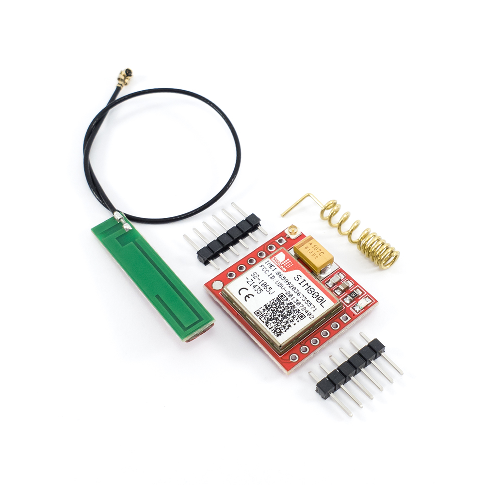
Features / Specs
- Board Variation: Type 1
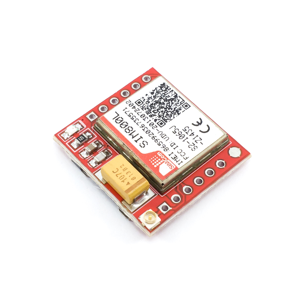
- GSM Module: SIMCom SIM800L (Refurbished Module – Tested & Guaranteed to be working)
- Guaranteed Firmware Version: 1418B06SIM800L24
- Supply Voltage Range: 3.4 ~ 4.4VDC
- Frequency Bands: Quad-Band (850/900/1800/1900MHz)
- Transmitting Power: Class 4 (2W) at GSM 850 and EGSM 900 / Class 1 (1W) at DCS 1800 and PCS 1900
- GPRS Connectivity: GPRS multi-slot class 12 (Default) / GPRS multi-slot class 1~12 (Optional)
- GPRS Data Transfer Speed (Max): Downlink (85.6kbps) / Uplink (85.6kbps)
- Compatible AT Command Sets: 3GPP TS 27.007,27.005 and SIMCOM Enhanced AT Commands
- Comms Interface: UART (1200bps to 115200bps)
- Firmware Upgrade: Supported via UART interface
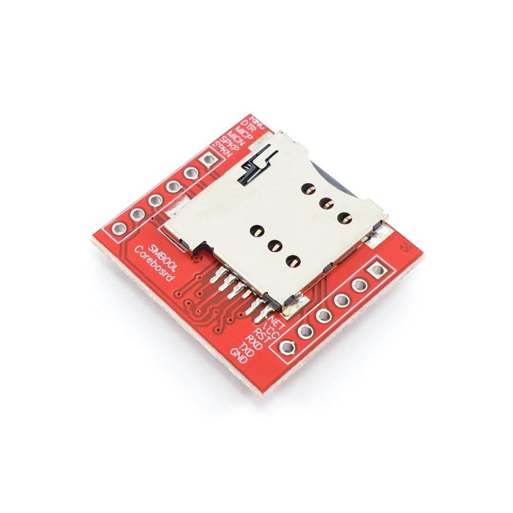
- SIM Card Slot: Micro SIM
- Operating Current (Typical in Sleep Mode): 0.7mA
- Operating Temperature (Approx): -40℃ to +85℃
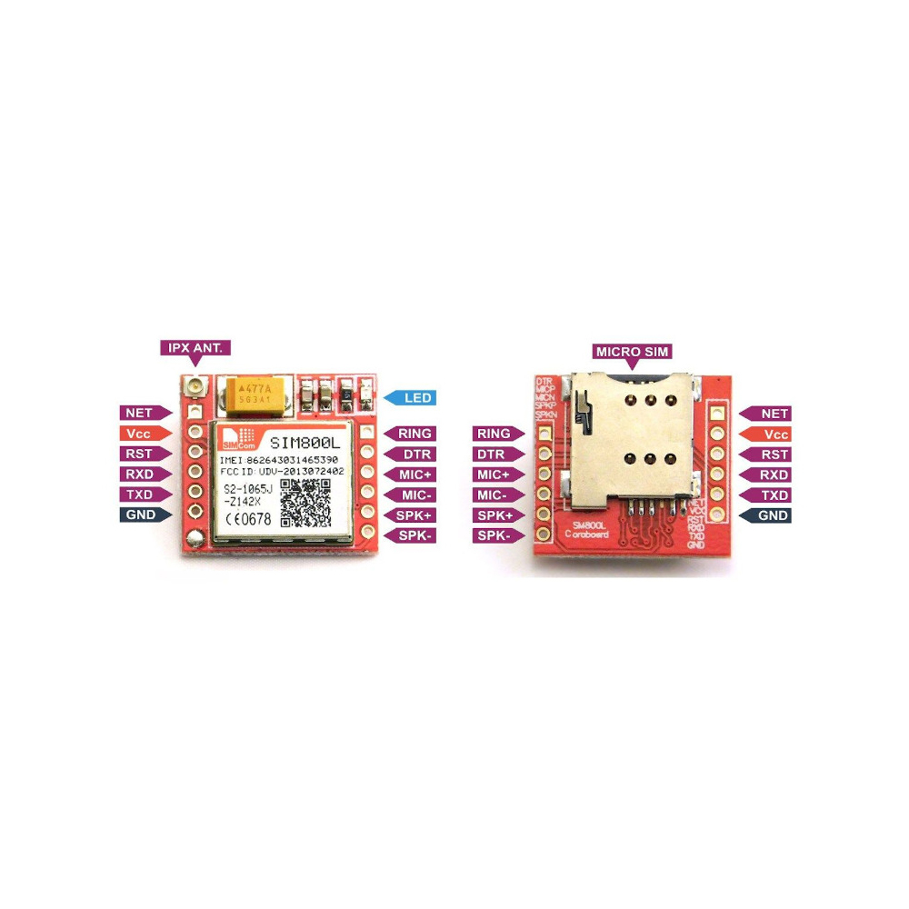
- Indication LEDs: Single LED which flashes quickly when not connected to a network and slowly when connected
- Header Pin Pitch: 2.54mm
- Dimensions: ~(25mm x 23mm)
Note on Refurbished Modules:As you may have noticed, the SIMCom modules used on these breakout boards are classified as refurbished. What this ultimately means is that the modules have been de-soldered from another device that may or may not have been in operation, and re-soldered onto the brand new breakout boards with the rest of the components being brand new as well. The modules are still fully operational and original SIMCom modules, but may have some marks and scratches on their labels (This happens during de-soldering). Any similar SIMCom module sold at this price point will almost always be using a refurbished module. Some manufacturers have even gone to the lengths of reprinting the module label so that they seem new, but if you look closely you should be able to see the original label underneath. We would like to be completely transparent regarding all the items we sell which is why we think it is important that we explain the above in such detail.
That being said, every SIMCom board we sell has undergone some basic quality control before we make them available to our customers. This includes a visual inspection, firmware re-flash to the above mentioned version, and a simple network registration check.
Pin Description
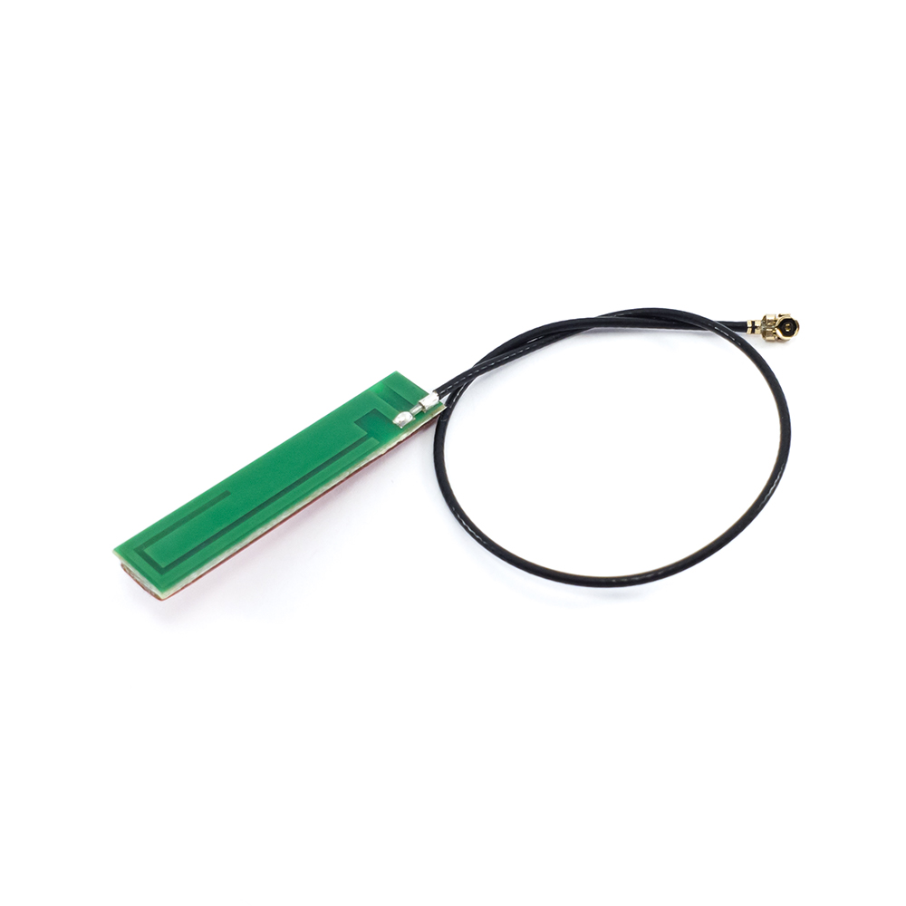
- NET-> External Antenna Connection
- VCC-> Supply Voltage (3.4 ~ 4.4VDC)
- RST-> Reset Pin – Pull LOW for more than 100ms to perform a hard reset
- RXD-> UART RX Pin (Connect to Microcontroller TX)
- TXD-> UART TX Pin (Connect to Microcontroller RX)
- GND-> Ground
- SPK--> Differential Audio Output Pin (Speaker -)
- SPK+-> Differential Audio Output Pin (Speaker +)
- MIC--> Differential Audio Input Pin (Microphone -)
- MIC+-> Differential Audio Input Pin (Microphone +)
- DTR-> Activates/Deactivates Sleep Mode – Pull HIGH to enable Sleep Mode, pull LOW to disable
- RING-> Ring Indicator Output Pin – Defaults to high, pulses low when a call is received

