Features / Specs
- Manufacturer: Shenzhen LC Technology
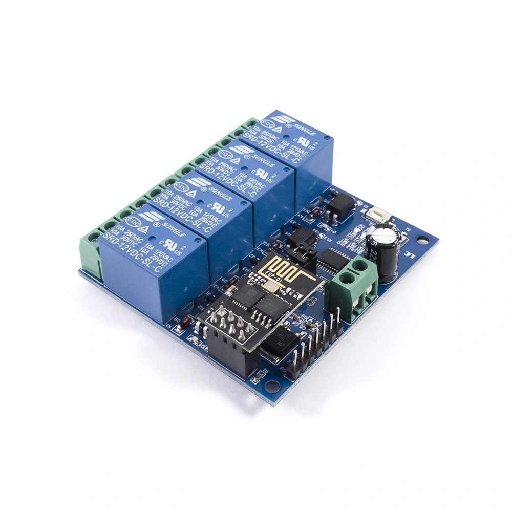
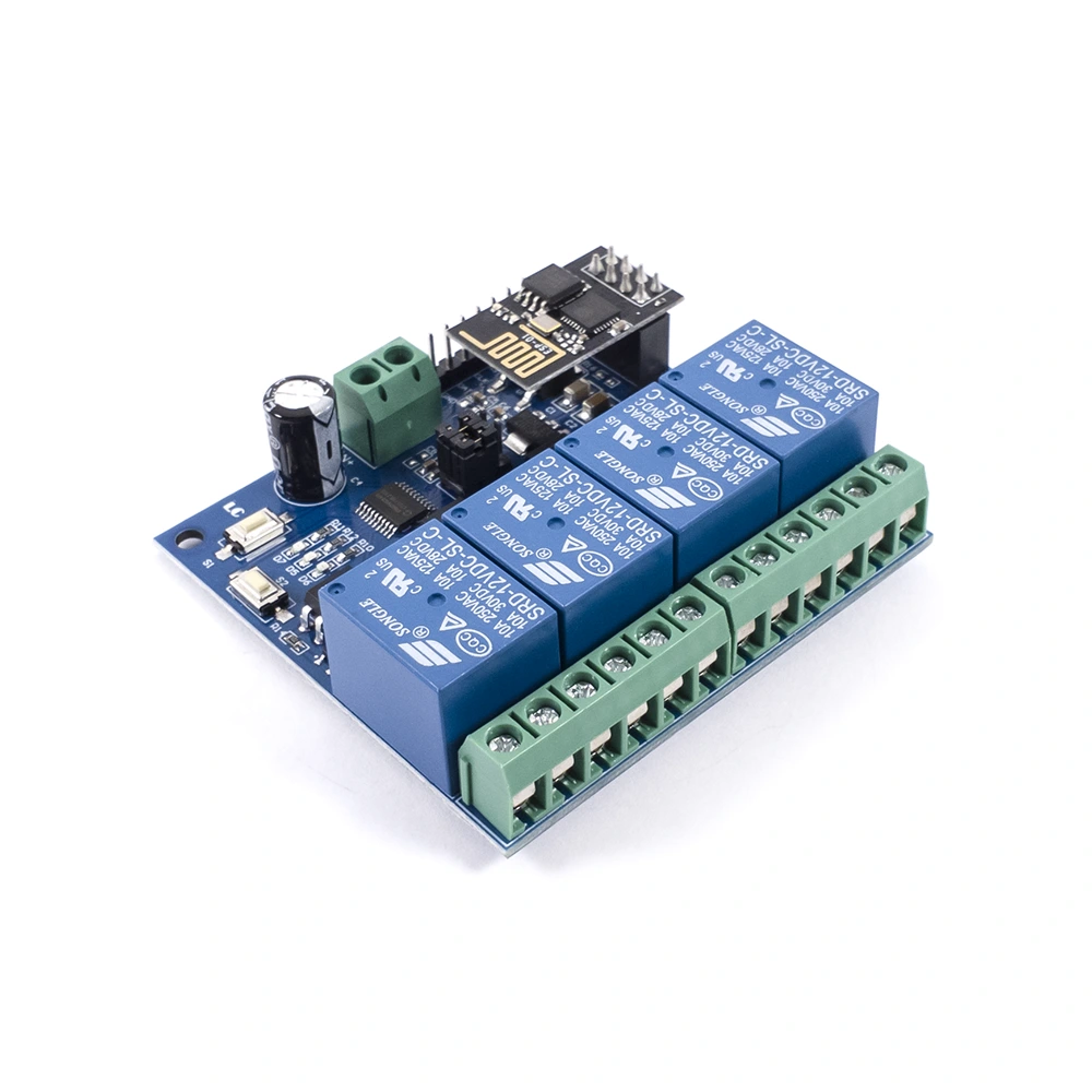
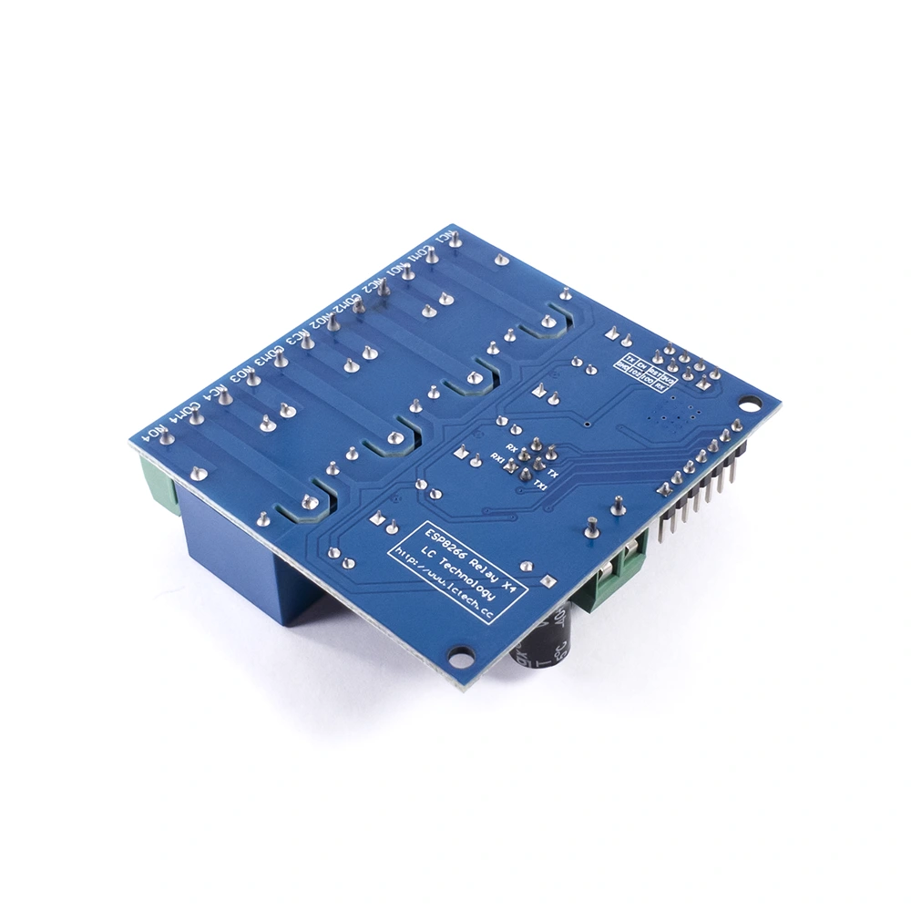
- Board Model: ESP8266_Relay_X4
- WiFi Module: ESP-01 (ESP8266EX)
- Microcontroller: 08H003F4P6 (Unknown Manufacturer) – Equivalent to STM8S003F3
- Supply Voltage: 12VDC (≥ 1A)
- Programming Interface: 7-Way SIP Header (Includes serial port pins)
- Relay Specs: 12VDC Coil; SPDT; 10A 250VAC / 10A 125VAC / 10A 30VDC / 10 28VDC
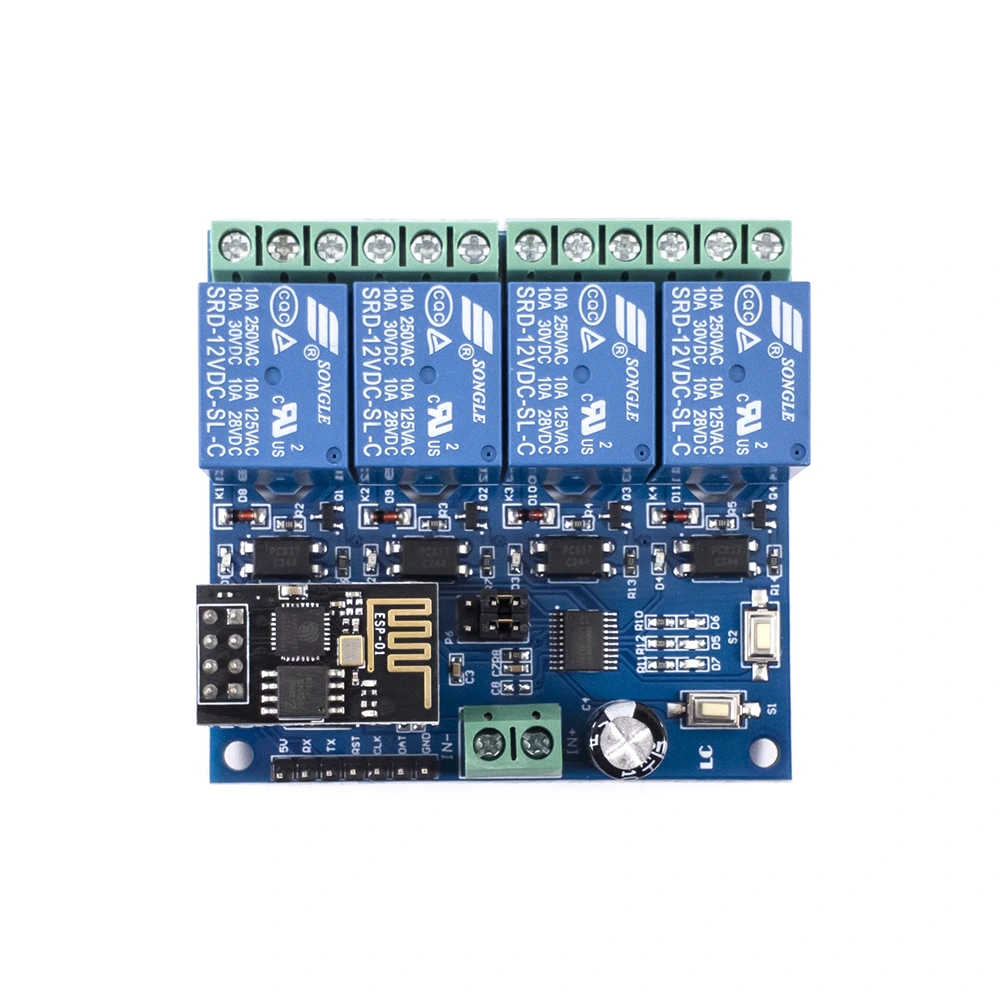
- Push Buttons: S1 (Mode Select; Default is Mode 1) / S2 (Reset)
- Indication LED’s: 4x Relay State LEDs / 2x Mode Indicator LEDs; D7 (Red) for Mode 1; D5 (Blue) for Mode 2 / 1x Working State LED (D6)
- Working State LED States: OFF – Being configured or disconnected from router / 0.5sec Fast Blinking – App is configuring WiFi account and password / 2sec Slow Blinking – Configuration complete, waiting for connection from App by TCP / ON – TCP connection with App successful
- Jumper Caps (P6): ESP8266 Mode (Default Mode) – RX->RX1 & TX->TX1 / USB Mode – RX->Unnamed Pin & TX->Unnamed Pin
- USB Mode Control Commands (Hex Format): Open Relay 1 – A0 01 01 A2 / Close Relay 1 – A0 01 00 A1 / Open Relay 2 – A0 02 01 A3 / Close Relay 2 – A0 02 00 A2 / Open Relay 3 – A0 03 01 A4 / Close Relay 3 – A0 03 00 A3 / Open Relay 4 – A0 04 01 A5 / Close Relay 4 – A0 04 00 A4
- Operating Temperature: -40°C to +85°C
- Dimensions: ~(63mm x 59.9mm x 19mm)
- Mounting Hole Diameter: ~3.1mm
- Mounting Hole Spacing (Center to center): ~56.7mm
- WiFi Chip: Espressif ESP8266EX
- External Flash Memory: 25Q80 (1-MB / 8-Mbit)
- WiFi Protocols: 802.11 b/g/n
- Frequency Range: 2400 – 2483.5MHz
- Hardware Features: UART / HSPI / I2C / I2S / IR Remote Control / GPIO / PWM
- RF Features: Integrated TR switch, balun, LNA, power amplifier and matching network
- Network Features: Integrated TCP/IP protocol stack
- Wireless Network Modes: Station / SoftAP / SoftAP + Station
- WiFi Security Modes: WPA / WPA2
Pin Description
- 5V-> 5VDC Supply (Output of onboard LDO)
- RX-> UART RX Pin for serial connection
- TX-> UART TX Pin for serial connection
- RST-> Reset Pin (ICSP for MCU)
- CLK-> Clock Pin (ICSP for MCU)
- DAT-> Data Pin (ICSP for MCU)
- GND-> Ground
Resources
- Espressif ESP8266EX Datasheet
- LC Tech ESP8266 Board User Guide – 12V
- LC Tech ESP8266 Board Schematic


