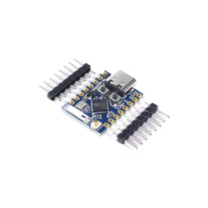


Features / Specs
- Manufacturer: Generic
- Main Chip: Espressif ESP32-C3FH4X (RISC-V 32-bit single-core processor, up to 160 MHz)
- Antenna: Onboard chip antenna – no external antenna connector
- Flash Memory: 4 MB (in-package)
- ROM: 384 kB
- SRAM: 400 kB (16 kB usable as cache; plus 8 kB RTC SRAM)
- USB Interface: USB Type-C, connected directly to the ESP32-C3’s native USB (USB Serial/JTAG controller, USB 2.0 full speed) – no USB-to-serial chip
- Power Input Options:
- USB Type-C Socket: 5 V
- 5V Pin: Power input/output, connected directly to the USB Type-C VBUS line; 4.3 – 6.0 V in, through the onboard BAT60J Schottky diode and ME6211C33 LDO regulator (full 500 mA from 4.3 V)
- 3V3 Pin: Regulated 3.3 V output from the onboard ME6211C33 LDO regulator; a 3.3 V supply can also be fed in here, bypassing the regulator
- Operating Voltage Range (Chip): 3.0 – 3.6 V (supplied at 3.3 V by the onboard regulator)
- I/O Logic Level: 3.3 V – inputs are rated to a maximum of VDD + 0.3 V, so the pins are not 5 V tolerant
- Communication Interface: USB / UART
- Bootloader Mode: Hold Boot while connecting USB, or hold Boot and press Reset
- Operating Temperature Range (Chip): -40 °C to +105 °C
- Storage Temperature Range (Chip): -40 °C to +150 °C
- Usable Peripherals (This Board): 13x programmable GPIOs (all PWM-capable) / 2x UART (UART0 on
GPIO20/GPIO21) / 1x I2C / 1x SPI / 1x I2S / 6x ADC channels - Full Chip Capabilities (Not All Exposed on This Board): 16x programmable GPIOs (the SPI flash pins are not bonded on this variant) / 3x SPI (SPI0 and SPI1 for flash, SPI2 general-purpose) / 2x UART / 1x I2C / 1x I2S / 2x 12-bit SAR ADC, up to 6 channels / 6x LED PWM channels / RMT, TWAI, GDMA, USB Serial/JTAG, temperature sensor
- Security Features (Chip): Secure boot / flash encryption / 4 kbit eFuse (OTP) / AES-128/256, SHA, RSA and HMAC acceleration / digital signature / random number generator / clock glitch detection
- GPIO:
- Usable: 13x programmable GPIOs on header pins
GPIO0–GPIO10,GPIO20andGPIO21 - Analog:
GPIO0–GPIO5(6x ADC channels) –GPIO5is on ADC2, which Espressif notes is not factory-calibrated and inoperable on some chip revisions; useGPIO0–GPIO4for reliable reads - Strapping Pins:
GPIO2/GPIO8(blue LED) /GPIO9(Boot button) – sampled at reset to set the boot mode, so keep external circuits from pulling them the wrong way at power-up; all three are pulled up onboard - Shared with USB:
GPIO18/GPIO19(USB D- / D+) – used by the USB Type-C port, not on the headers - Debug: USB Serial/JTAG over the USB Type-C port; JTAG is on header pins
GPIO4–GPIO7(MTMS/MTDI/MTCK/MTDO)
- Usable: 13x programmable GPIOs on header pins
- Onboard Peripherals:
- Buttons: Reset / Boot (
GPIO9) - LEDs: Blue user LED on
GPIO8, lit when driven low / red power LED
- Buttons: Reset / Boot (
- Dimensions (L x W x H): ~(22.52 x 18 x 4.1 mm)
- Number of Pins: 2x 8 pins (16 total)
- Header Pin Pitch: 2.54 mm
- Pin Row Spacing (Centre to Centre): ~15.24 mm
- WiFi Standards: IEEE 802.11b/g/n
- WiFi Frequency Band: 2.4 GHz
- WiFi Channel Bandwidth: 20 MHz / 40 MHz
- WiFi Data Rate (Max): 150 Mbps
- WiFi Transmit Power (Max): +21 dBm (802.11b) / +20 dBm (802.11n)
- WiFi Modes: Station / SoftAP / Station + SoftAP / promiscuous
- WiFi Security: WPA2-PSK / WPA2-Enterprise / WPA3-PSK / WPA3-Enterprise
- Bluetooth Version: Bluetooth 5 (LE), Bluetooth mesh
- Bluetooth Data Rates: 125 kbps / 500 kbps / 1 Mbps / 2 Mbps
- Bluetooth Transmit Power (Max): +20 dBm
- Bluetooth Receive Sensitivity: -105 dBm @ 125 kbps / -93 dBm @ 2 Mbps
- Bluetooth LE Features: Advertising extensions / multiple advertising sets / simultaneous advertising and scanning
- Antenna Sharing: WiFi and Bluetooth share the one antenna, through the chip’s internal coexistence mechanism
Resources
- NOTE: Datasheets and schematic are for reference only – the manufacturer of this board and its supporting parts is unconfirmed.
- Espressif ESP32-C3 Product Page
- Espressif ESP32-C3 Series Datasheet
- ESP32-C3 SuperMini Schematic